Difference between revisions of "Fluorescence-Sensor"
| Line 4: | Line 4: | ||
|product type=O2k, MultiSensor, O2k-Fluorescence LED2-Module | |product type=O2k, MultiSensor, O2k-Fluorescence LED2-Module | ||
|info=[[O2k-Fluorescence LED2-Module]] | |info=[[O2k-Fluorescence LED2-Module]] | ||
|product image=[[ | |product image=[[Image:Fluorescence-Sensor Green.JPG|180px|right|link=http://www.bioblast.at/index.php/Fluorescence-Sensor]] | ||
}} | }} | ||
__TOC__ | __TOC__ | ||
Revision as of 14:10, 13 November 2013

![]()


Fluorescence-Sensor

| Description | Fluorescence-Sensor: LED with specified wavelength, photodiode, Filter-Cap attached with specific optical filter for the LED and/or photodiode. See Fluorescence-Sensor Green and Fluorescence-Sensor Blue. |
|---|---|
| Product ID | 442## |
| Type | O2k, MultiSensor, O2k-Fluorescence LED2-Module |
| Link | O2k-Fluorescence LED2-Module |
| Image | 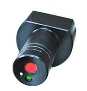 |
O2k-Guide
Select the Fluorescence-Sensors
Switching between different excitation wavelengths and filters is achieved by simply exchanging the fluorescence sensors. Two types of optical sensors are supplied with different LEDs for fluorescence excitation, and the effective spectra of the LEDs are modified by filters. Please select the necessary fluorescence sensor and filter set form the table of application specific settings. Each fluorescence sensor is delivered with a filter set already in place:
- Fluorescence-Sensor Green: 525nm. The installed Filter-Cap is ready for H2O2 measurement with Amplex® UltraRed.
- Fluorescence-Sensor Blue: 465 nm. The installed Filter-Cap is ready for measurements of mt-membrane potential with safranin. A different filter is used for measurement with Magnesium green® or Calcium green® .
O2k-Guide: Setup - next step Mounting a Filter-Cap
Connect Fluorescence-Sensor to O2k
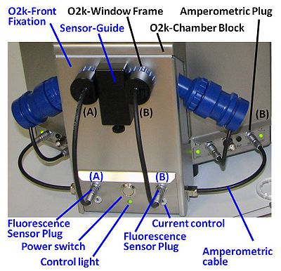
For recording of fluorescence signals, insert the black sensor into the window of the O2k chamber as far as possible, aligning the Sensor-Guide Sector with the Sensor-Guide of the O2k-Front Fixation. Then connect the cable of the Fluorescence-Sensor to the Fluorescence-Sensor Plug of the Fluorescence-Control Unit. Removing a Fluorescence-Sensor from the O2k chamber: Remove the Sensor-Guide to allow rotation of the sensor. Pull out the Fluorescence-Sensor while rotating it. Do not pull on the cable. Replace the Sensor-Guide.
Stoppers
Use only black PEEK stoppers in conjunction with fluorometric measurements. If necessary, replace the previous white PVDF stoppers. The black stoppers can be used for all HRR applications in general. See MiPNet12.06 for calibration of the O2k-chamber volume, which is identical for PEEK and PVDF stoppers.
O2k-Guide: Electronic settings